|
|

|
LORD OF THE RING
|
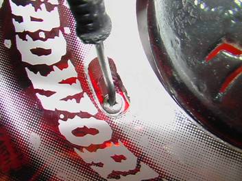
| Judge Dredd was a game with a problem. During the testing phase of game development, operators became concerned with the operation of the Deadworld and in particular, the multiball ball locking mechanism. The game as originally envisaged placed the three balls as they were locked in holes on a slowly rotating ring around the Deadworld. When the third ball was locked, they were released by a mechanical arm and dropped onto the playfield. This was how it worked in the original software ROM. The problem arose if the arm - or the magnet it contained - failed to work. This would mean there was no way to release the balls, so the software was changed to only lock the third ball on the ring - the first two sailed past the ring entrance and became "virtual" locks instead. In addition, the ring was changed so the holes became slots. That way, if a ball erroneously ends up on the ring, as it turns, the ball will simply fall off. In a home environment though, the potential for the arm to fail is minimised so wouldn't it be nice to restore the functionality and make the ball lock work as originally intended? One man thought so. Adam Gould set about discovering how to restore the feature, and here he tells Pinball News all about it.
Judge Dredd Dead World Locking Project I will never forget the disappointment I experienced when I first saw that the three ball locking on the Deadworld had been disabled. I had previously looked on the rec.games.pinball newsgroup to see if anyone had been able to restore the Deadworld, but no one could find the original ROM. Then in October of last year I saw that The Shoot 'M Again team had uploaded the Rom to the Internet Pinball Database. I installed the ROM chip only to find that no balls were diverted to the Deadworld not even the third! Originally the prototype Judge Dredd had an opto switch near the entrance to the left ramp (switch 32), later this switch was moved up the ramp and changed number to switch 67. The next step was to try to convert switch 67 back to 32 (switch 67 was not used on the production L_1 rom). Opto switches consist of a transmitter and receiver and need a separate opto board on the Judge Dredd pinball. In order to make the switch number change I needed to use a spare opto switch (65). In the modification switch 65 became column 3 and 67 was linked to row 2 to make 67 become 32. Below is the circuit diagram of the modified board. You can click on it for more detail. The next task was to make the new locking ring with holes instead of slots. I did this using a router and a circle cutting jig. This produced the ring, then the holes were drilled using a 22mm flat cutting bit.
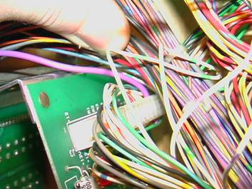
Installing the Opto Board - Reinstall the board into its original position - The picture shows the large multiconnector that plugs into J3 on the opto board.
- First you need to remove the white-green wire from J3 pin 9, labeled R5.
- Next take the provided wire and insert it in to the multiplug corresponding to J3 pin 9. This can be done using a small flat head screw driver or an IDC insertion tool.
- Run this wire to switch 38 subway enter 2. Cut the wire to length, strip the end and solder it to the lug with the green-orange wire attached.
- Reconnect the multiplugs to the circuit board.
- Go into switch edge test and break switch 67 left ramp enter and it should register as switch 32.
- Undo the three screws holding the ring assembly to the three-pronged cradle. Note their rough positions in the slotted hole.
- Undo the three locking nuts on the lower ring and remove ring - Install new ring. - Reinstall the assembly back on the dead world. - Go to test 15 Planet Arm Test and position the ring so that the ball is underneath the crane. The crane height may also need adjusting.
If you have any problems please email me at: [email protected]
The first kit costs $70 plus shipping and includes the new red ring and the original ROM along with fitting instructions. The second kit consists of the ring, the ROM, instructions, plus a new modified opto board ready for you to fit. This kit costs $225 plus shipping. Details of kits including payment methods are on the AJ Pinball website.
|