| HANDHELD INFRARED
BEAM TESTERS
PURPOSE
I wrote this article because the need for, or at least the question about, testing Infrared (Ir) diodes and transistors in pinball machines has been reoccurring on RGP for years. See this example from 1994 and this example from 2005. Ir diodes and transistors have been used as switches in pinball machines since 1987.
To verify properly operating Ir optical switches and to troubleshoot the invisible infrared beam used buy those switches, I have personally been using a variation of the wise solution that the Editor of Pinball News (Martin) has previously suggested, for at least five years before he posted his suggestion. So, I know my Pinball Renaissance version works.
I made myself a set of battery powered hand held testers (Ir Sender and Receiver) for troubleshooting intermittent or bad Ir diode and/or transistor circuitry and components. My testers are easy to use. They are especially great for troubleshooting intermittent Ir problems and for aligning long-shot optos like the one used on Dracula.
I put my sender and receiver each in a small plastic housing with a 9 Volt battery panel. I used visible red LEDs as indicators of the invisible Ir beam.
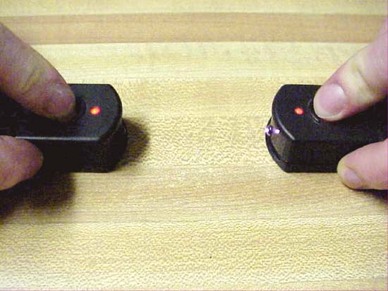
The Ir Receiver on the left is looking at the beam from the Ir Sender on the right.
OTHER Ir TESTERS
Though other things, such as digital cameras and Ir sensor cards, can be used to look at the Infrared beam that is invisible to the naked eye, because you can make your own version of the IR sender and receiver that I made for myself, once made they are constantly available and ready to use. This is not true with the Ir sensor cards. The Ir testers that I use are smaller and a lot less expensive than a video camera. And they are easier to use than a digital camera. The Ir cards and Ir sensitive cameras can only detect an Ir beam. They cannot send a beam; like the Ir sender.
USES
I have been repairing pinball machines for over ten years. During those years, there have been several, if not many, occasions when my little Ir sender and receiver have been very useful. One example, previously mentioned, is during the alignment of the long-shot opto for Mist Multi-Ball (Kevin Martin) on Dracula. The Receiver may also be used to test for working Ir remote controls of all types and uses. The Ir sender can be used to check some Ir controlled toys. Use of these testers can save the time and haste of opening the battery compartments on the devices under test.
ALIGNMENT
During Mist Multi-Ball, the moving target ball is meant to follow the same path as the invisible beam from the long shot sender. If both parts of this opto system are not almost completely parallel, the machine may malfunction or give a random Multi-Ball mode.
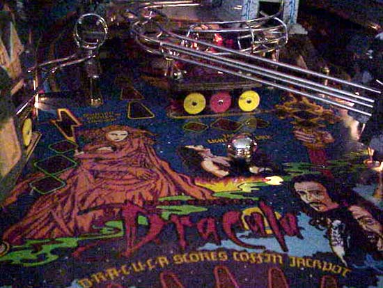
The Ir Receiver can be used to track and collimate the invisible beam from the long shot sender all the way to its receiver across the entire width of the playfield.
TROUBLESHOOTING
The Ir testers can be used to troubleshoot intermittent Ir Senders and Receivers of WMS ball troughs.
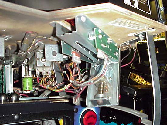
The Ir receiver (transistor) board is on the left and the Ir sender (diode) board is on the right.
Heat and vibration from normal game play can loosen the dropping resistors and Ir LEDs. When these components get loose the game may give a ball(s) missing message at start-up or random Multi-Ball during play.
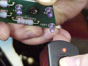 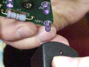
On the left, the visible red LED is lit, indicating presence of the Ir beam from the bottom right Ir LED. On the right, the visible red LED is dark, indicating absence of the Ir beam from the bottom right Ir LED after I wiggled the lens of that LED.
CIRCUITS
From the following enhanced picture, you can get some idea of how tiny the Ir circuits are. Consider that the picture shows both of the slightly more parts intensive improved Ir circuits.
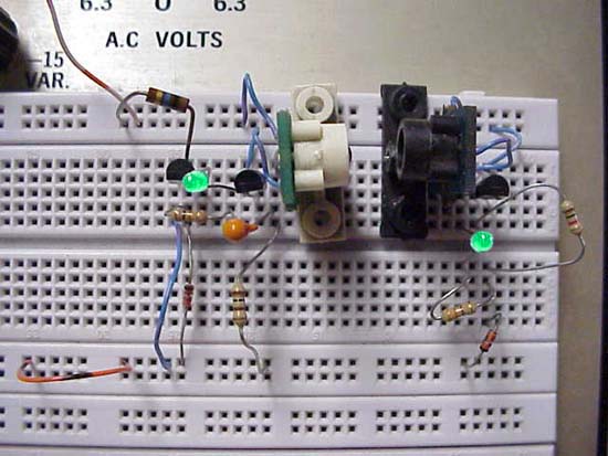
On the left side, is the circuit for the Ir sender. Here the lit green LED shows that the Ir beam is being produced. On the right side, is the circuit for the Ir receiver. And again, a green glowing LED shows presence of the Ir beam.
I designed two versions of both the Ir sender and the Ir receiver. Both the sender and receiver have basic and improved versions. The improved versions are the ones that I built to troubleshoot tricky Ir switch problems.
Both the sender and receiver circuits draw only about 5.0mA. So, unless your kids play with the testers, you should only need to replace the batteries as you should replace the batteries in your pinball machines; once a year. Even with the tiny amount of current used to run either of the circuits, either can be used from a distance up to about 2.5 feet (about 75 cm).
Because these little circuits are simple to build, I decided not to provide parts lists. With the exception of the opto parts, the majority of the components are standard value parts that should be fairly easy to purchase. All of the parts can be easily viewed in the following schematics. Each version of the two circuits has its own schematic.
Though I did not provide parts lists, I did provide parts substitution lists and parts suppliers. I personally recommend Ed of Great Plains Electronics - GPE. Should you decide to make your own Ir testers, GPE should have the majority of the parts.
PARTS SUBSTITUTIONS
2N3904 Transistor (General Purpose NPN) Substitutions
2N4401
2N5551
MPSA06
NTE123AP
2N3906 Transistor (General Purpose PNP) Substitutions
2N4403
2N5401
MPSA56
NTE159
9 Volt Battery By Other Names
PP3
1604
6LR61
9 Volt Cell Battery
9 Volt Transistor Battery
Capacitor Substitutions
The only capacitor (C1 in the schematic of an improved Ir sender) can be substituted for any near value cap that is rated for at least 10.0 Volts DC. Though this cap can be substituted, changing this cap's value will change both the frequency and duty cycle of the pulsed Ir output.
NOTE: You must remember to observe polarity, the direction the cap gets placed into the circuit, if you use electrolytic or tantalum capacitors.
Ir LED (Sender)
Industry PN: QED123
Radio Shack PN: 276-143 or 276-143C
WMS PN: A-14231
WMS PN: A-16908 (assembly with bracket)
Side looking photodiode for getting into smaller spaces like the small slot in between opto-interrupters; as used on drop targets and flipper optos.
Ir Transistor (Receiver)
Industry PN: QSD124
Radio Shack PN: 276-145 or 276-145A
WMS PN: A-14232
WMS PN: A-16909 (assembly with bracket)
Side looking NPN phototransistor for getting into smaller spaces like the small slot in between opto-interrupters; as used on drop targets and flipper optos.
Resistor Substitutions
Any of the resistors may be 10 or even 20% tolerance. Any of the resistors may be rated for 1/4 or 1/2 Watt. NOTE: It is best to keep R1/R2 (330 Ohm) and R3 (330 Ohm) 1/2 Watt resistors. But, as these testers will normally be pulsed for a short duration, 1/4 Watt resistors will work for this application.
PARTS SOURCES
Pinball Parts Suppliers - US
Great Plains Electronics
Pinball Life
Pinball Parts Suppliers - OUS
Pinball Heaven
Electronic Parts Suppliers - International
Electronic Goldmine
Radio Shack
SCHEMATICS
Schematic of an Ir receiver
Schematic of an improved Ir receiver
Schematic of an Ir sender
Schematic of an improved Ir sender
OPERATION
The Ir Receiver
The visible LED will glow dimly in ambient room light. And, it will light more brightly when it detects an Ir beam. The receiver is sensitive enough and has a quick enough response time to pulse with modulated Ir signals; such as the signal from the Improved Ir sender or remote controls for television sets.
The Improved Ir Receiver
Like the more basic Ir receiver, the visible LED on this improved receiver will glow dimly in ambient room light. And, it will light more brightly when it detects an Ir beam. But due to the additional stage on this receiver, it is even more sensitive to Ir light. So, it can more easily detect Ir light from a greater distance than its more basic counter part. Either receiver should be useful as a troubleshooting tool for testing Ir LEDs used in pinball machines. This receiver is also sensitive enough and quick enough to see the pulses of modulated Ir signals.
The Ir Sender
The Ir sender simply sends a constant and narrow beam of Ir light with a wavelength of about 880nm.
The Improved Ir Sender
The Improved version of the Ir sender gives a modulated square wave pulse
of about 3.0Hz with a 25% duty cycle. This flashing pulse is unlike any
signal or diagnostic LED pulse used in any pinball machine.
NOTE All pictures in this article are courtesy of Lloyd at SS Billiards.
 Back to the learn page Back to the learn page
Back to the front page
© Pinball News 2006
|