|
|

|
ENLIGHTENING
|
| In this second article, Todd "Pinted" Andersen, President of the TCFPA continues his look at the history of pinball lighting by examining the solid state alternative to lamps. L-E-Ds used in P-I-Ns
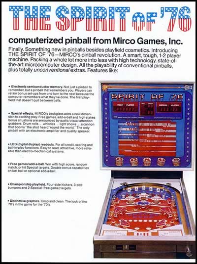
First game to use LEDs in any capacity was probably the 1975 Spirit of 76, by Micro Games.
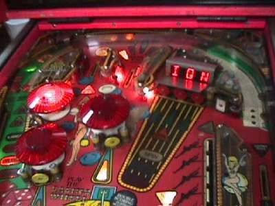
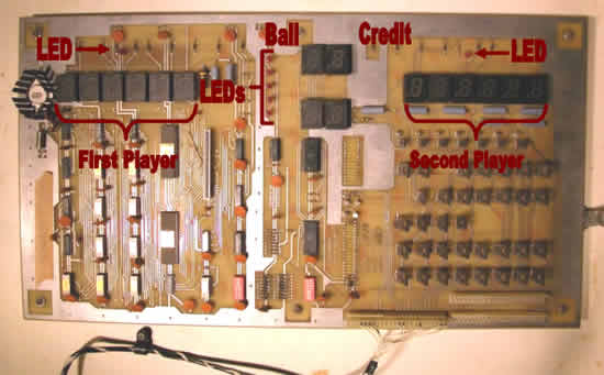
The large black rectangles across the top make up the: first player, ball, credit and second player 7segment LED displays. The five vertically situated red dots' in the top center of the board are red LEDs. There are also two more red LEDs on top-left and top-right sides of this board.
Williams (WMS) was probably the first to think of using a beam of infrared light to replace a mechanical switch in pinball machines. Even though only one hundred “Star Light” games were ever made, production with WMS “System 7” started in June of 1984. Later that year, System 9 was used in some Star Light machines. With this new system, Star Light was probably the first pinball machine that was slated to, but never used optos in its game’s design. The CPU board was set up to support the use of optos, but optical beam used as switches was not implemented at this time.
First pinball machine to use IrLEDs to sense switching was probably WMS Millionaire. Optos weren't actually used as switch detectors until about 2 1/2 - years after System 9 was introduced. Optical switches were used on the second game after System 11A was introduced in October of 1986. Millionaire was made in January of 1987. Optical interrupters were first used on Millionaire's drop target boards.
The first game to use visible LEDs on the playfield was probably the 1990 Vegas, by Premier Technologies. The PF toy, a slot machine', used 7segment LEDs.
A diode is a solid-state electronic device that only allows current to flow in one direction.
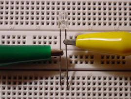
In the picture on the left, the diode will not allow the flow of electricity; therefore, the lamp is not lit. In the picture on the right, the inverted diode is allowing the flow of electricity; and allowing the lamp to light. The word LED is an acronym for Light Emitting Diode. A LED is like a normal diode, but it has many differences. One difference is that a LED emits photons (light).
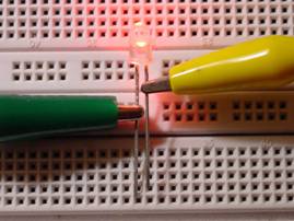
In the picture on the left, electricity will not flow through the LED; therefore it is not lit. In the picture on the right, the LED is flipped and electricity will flow through the device; therefore it lights.
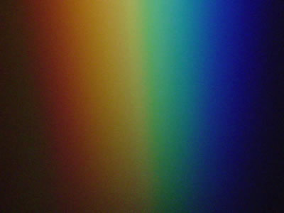
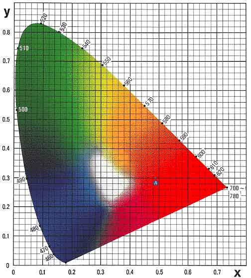
Unlike LEDs, incandescent lamps produce white light. White light is made up of all colors of light combined. White light can be 'split' into each of its combined colors. This is the case in the above picture. In the picture a glass prism was used to split the white light into its component colors.
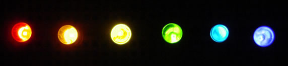
Most LEDs only omit one color of light. Different diodes must be used for each color desired. This is the case in the picture above. Six different diodes were lined up to create this LED rainbow'.
Unlike most incandescent lamps, some diodes are capable of emitting light that is beyond our spectrum of sight. Diodes that emit infrared light are used in some pinball machines. This beam of light is used as part of the system that detects the location of the ball inside the game. This is the physical location of the actual pinball. The physical location reflects: target hits, scoring, and game play.
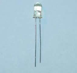
This article will only deal with one type / style of LED. This is an axial leaded T 1 3/4 (5 mm) LED. Production techniques differ from manufacturer to manufacture; therefore not every LED is built the same.
Close up of an IrLED with a clear body. The above diagram is not to scale and does not include all components of a LED. Lens: Body / Dot: Base / Flat Spot: Cathode Lead: Anode Lead: The components shown above are merely for identification of polarity marks. The polarity is the direction the device must be orientated in the circuit. The only way to be sure of proper orientation of a LED is to check it electrically.
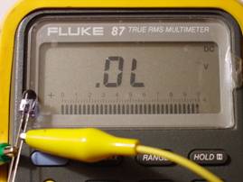
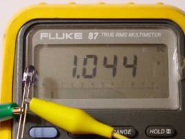
A digital multi-meter can be used to check the polarity of most LEDs. As the beam of light from IrLEDs cannot be seen with the unaided eye, this is particularly useful when checking IrLEDs for polarity and to help ensure that they work electrically. In the picture on the left, with the leads one-way on this IrLED, the meter shows OL' . This indicates that no current can flow through the device. With the leads connected the other way around, as shown in the picture on the right, the meter shows the normal measurement for an IrLED with a reading of about 1.0 Volt.
The above schematic symbol shows the connections to the power (+) and ground (-). It also shows double bent arrows' that signify that light is coming from the diode.
A fun place to learn more about LEDs and different types of LEDs is the on-line "LED Museum".
Most visible light LEDs draw 2030 mA of direct current and require 1.33.9 Volts to operate. Most infra-red LEDs, or IrLEDs, draw 2030 mA of direct current and require 1.01.2 Volts to operate. As a one or two volt supply is not readily available in pinball machines, each LED is usually connected to the positive 12 Volt supply. In this case, a dropping' resistor is used on each LED. This resistor safely drops' the excessive voltage from the supply, leaving the correct voltage for each LED.
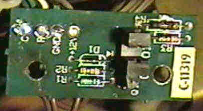
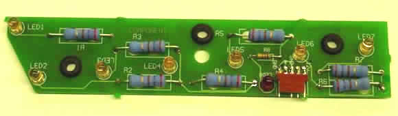
The large blue piece-of-candy' looking components in this picture are 270 Ohm, 2 Watt dropping resistors. Each LED is hooked up to +12.0 Volts and makes its connection to ground through its resistor. Each LED only requires about 1.0 Volt to operate. So, the remaining 11.0 Volts gets dropped' across each LED's resistor.
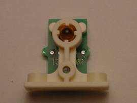
The IrLED on the left (sender), shines a beam of invisible light over to the IrTransistor on the right (receiver). Notice how the sender protrudes out of its housing and the receiver is recessed into its housing.
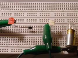
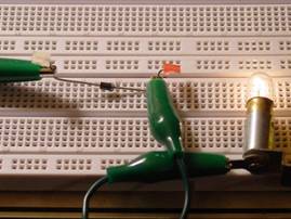
Due to the type of technology and narrow beam, use of infrared light in pinball machines is limited to line-of-sight' use. When the infrared sender and receiver are collimated, the beam can go from the LED to the transistor and optically energize the transistor. This is shown in the picture on the left and simulates an opto receiver in its on state. When turned on by the infrared beam of light, there is about 1 to 1.5 Volts across the receiver. The red LED indicator is dark, signifying no switch closure. When the beam is blocked by the pinball, the transistor turns off. When off, there are about 11.0 Volts across the receiver. The red LED indicator is lit, signifying a switch closure. This is shown in the picture on the right. In both pictures, the green indicator LED is constantly lit. The green LED is a visible indicator of the infrared beam. And lastly, there should always be about 1.0 Volt across a powered IrLED. Removing / Installing LEDs are usually mounted on boards. Because of this, special tools and technical knowledge is required when replacing LEDs. Unlike miniature incandescent lamps, LEDs have polarity. This means that they can only be correctly installed in one direction. If installed backwards' they get instantly damaged and must always be replaced. The intended purpose of this article is an introduction to LEDs. Replacing LEDs in pinball machines usually requires some sort of board work; and will not be covered in this article. But, as an aid, I will list tools used while replacing IrLED or common LEDs.
Tools (clockwise) 1) Soldering iron 2) Phillips Screwdriver Set 3) Solder Sucker 4) Needle Nose Pliers 5) 6 Curved Hemostat 6) Electronic Test Equipment 7) Standard Nut Driver Set 8) Standard Screwdriver Set 9) Solder
When working on a pinball machine, never perform any work, including just changing one of these little, often mistakenly named, solid-state light bulbs', when the game is powered on. It is recommended that you take some sort of technical training before attempting any circuit board repairs. It is also recommended that you practice on electronic kits before you work on pinball boards.
Unless otherwise noted all: charts, diagrams, pictures, and scans, courtesy of Pinball Renaissance - TCFPA . Also unless otherwise noted, all pictures taken with a Sony 3.3 mega-pixel MVC-CD300 digital still camera set to take fine pitch JPGs in: auto, inside, micro mode.
|
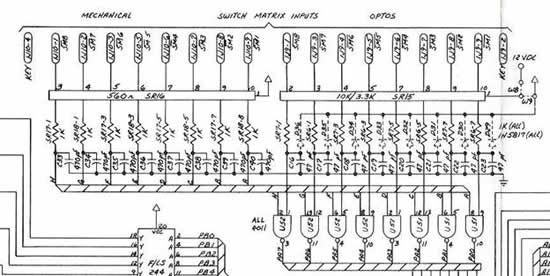 Schematic scan opto portion of WMS System 9