|
|

|
MORE BRIGHT IDEAS
|
|
Pinball News readers may have heard about the kits available for Attack From Mars owners which add LEDs to the mini flying saucers like the large saucer. That got me thinking about doing something similar for my Revenge From Mars. Being a cheapskate I was looking for a way to make it myself and perhaps add a couple of other mods along the way. There are some obvious problems with this saucer idea. RFM doesn't have a big saucer to copy - there are only two mini-saucers over each slingshot - and when do the LEDs come on? I did a web search and found this 10 LED sequencer at this web site:
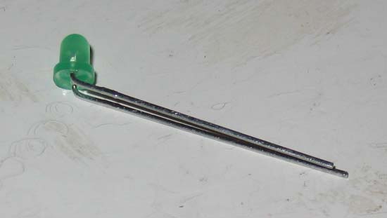
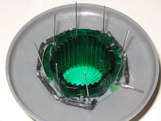
The 4017 does the sequencing and the 555 is the clock. The 47K resistor and the 1uF capacitor set the speed at which the LED's change, so I replaced the 47K resistor with a 100K variable resistor so the speed could be adjusted. But before making the circuit, the LEDs had to go into the saucers. A standard has eight small holes around the flasher done and they're exactly the right size for 3mm diameter LEDs like this.
Green LEDs seemed most appropriate. I could have used white ones but they'd probably be too distracting so green it was. The LEDs are a tight fit and a couple of holes needed filing a little to clear them out. There's also not much room between the LEDs and the flasher dome so the LED leads needed bending quite sharply. I bent them so the short cathode lead was always on the same side to make wiring easier.
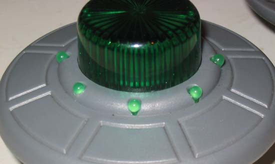
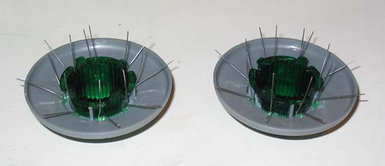
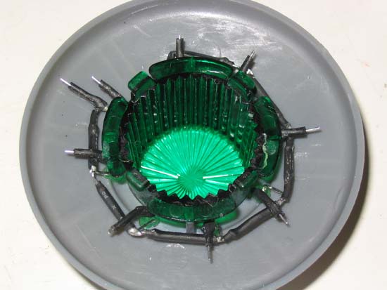
Despite being a tight fit, I put a very small dab of super glue on the edge of each LED to hold it securely in place. After fitting all eight LEDs the two saucers looked like this.
The leads pushed down on the surface of the saucer are the cathodes and they will next be connected together.
I've put some heat shrink sleeving on the cathode leads to prevent accidental shorts and then did the same to the anode leads before cutting them to the correct length.
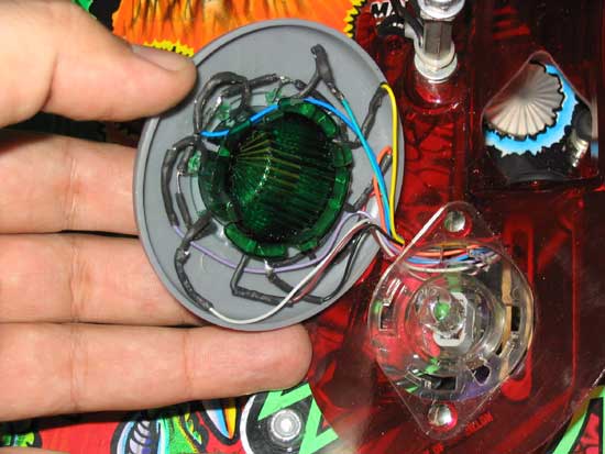
All that remains for the saucers is to solder on the connecting wires. For this I chose a 9-way domestic video interconnect cable because it has the right number of ways and it was also sheathed in black plastic which helps hide it. There was no suitable hole to run the cable from the top of the playfield to the bottom so I drilled a hole in the red plastic ramp and pushed the cable through to the underside.
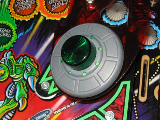
The hole is hidden when the saucer is replaced making a neat finish.and the saucer can still be removed to replace the flasher lamp.
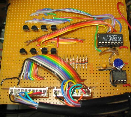
One final point on the saucers. I wanted them to spin in opposite directions. You'll see why later but I just reversed the order of the connections under the saucer making sure the first LED is always at the top when fitted. Now back to the driver circuit. I built it on stripboard for simplicity and although it's not the prettiest solution it does work.
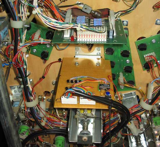
The 555 is the small 8-pin IC and the blue variable resistor next to it adjusts the speed of the LEDs. One important modification was needed because the circuit is designed to run 10 LEDs and the saucers only have eight, so the ninth LED output (pin 9) is connected to the reset (pin 15). I used 0.1" connectors for the saucer cables so they could be removed easily. The circuit board was mounted under the playfield on the bracket holding the ramp flap.
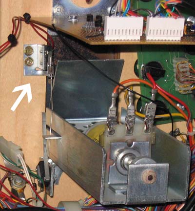
As you can see, the cables are routed along the same paths as rest of the wiring and secured with tie wraps. Two more things have to be considered. When is the circuit energised and how is it powered? I thought it would be good if the saucers lit up when the ramp is raised. Also, by having the saucers rotate in opposite directions they could guide the eyes to the ramp and give an additional visual cue. Although it would be possible to tie this board into the system's switches, I liked the idea of keeping the mod isolated in case it caused any problems, so I mounted another microswitch which is triggered when the ramp is raised and used that to switch the +5V power to the board. The switch is shown in the picture below.
That power is available from the PC in the backbox but to keep the circuit as isolated as possible from the rest of the game, I plugged a small plug-top power supply into the service outlet. Once I'm totally happy with the long term reliability of the circuit I'll change the wiring.
While I was fitting the saucer LEDs, I also put some LEDs in another part of the game.
Yes, the Martians have LED eyes and they are connected to the solenoid which jumps them up and down, so they flash when they jump. These LEDs are 2mm ceramic based devices which have very fine leads and need to be carefully positioned. The existing eyes were drilled out and holes made all the way through to the back of the Martian's head. The leads run through the back of the head and down through the body, exiting where the mounting bracket is inserted.
The two LEDs are connected in series but with the solenoid voltage ranging between 50V and 80V it was important to use a suitable series resistor, in this case 3K3. This idea came from John Blakeley who has modded a couple of Attack From Mars games in this way, being even more effective with four Martians to RFM's two.
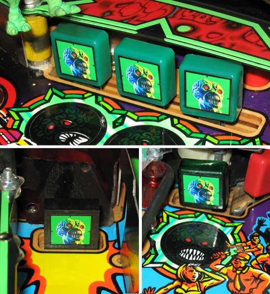
As a finishing touch, I put on some target stickers I was given by Chris Williams on the green standups and the drop target.
So there are three possible modification for a Revenge from Mars ranging in complexity. The saucer and Martian eyes LEDs are nice because a newcomer probably won't notice them until they light up while the stickers make the plain green targets more attractive and make the drop target more visible.
|