|
|

|
NEXT WMS FLIPPERS
|
|
By Todd "PinTed" Andersen In a previous article covering Williams - WMS Sys 6/7 flippers, it was explained that the neck of the original flipper link kept the return spring straight while the spring compressed during a flip. This is the WMS C-8230 / C-8270 flipper system. In this article, mainly covering flippers for WMS Sys 9 through WPC, the link holds the top of the conical return spring while tabs in the retaining bracket hold the bottom. In this later system, both components work in conjunction to collapse the return spring flat. This is the WMS C-13174-L/R flipper system. Directly below is a complete list of older Williams pinball machines that were originally built with the C-13174-L/R flipper system. The list is arranged by system. Each of the four systems is broken into sub-systems when applicable. The systems/sub-systems are listed chronologically by date of release. The games in each of the systems/sub-systems are arranged alphabetically.
The C-13174-L/R flipper system was used on the last two WMS Sys 7 games. But, it was mainly used on WMS Sys 9 through WPC games.
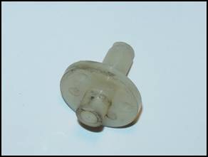
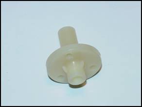
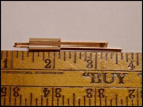
Plunger / Pawl / Crank
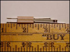
The length of both plungers is the same. The plunger with the correct flipper link is, pictured on the right. The correct part has a tapered neck. This taper holds the top of the return spring and allows the spring to collapse without over winding. The neck of the incorrect part, pictured left, can put too much pressure on - or even break - the return spring.
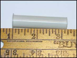
Coil Sleeve
The original flipper coil sleeve, pictured on the left, is the same number as the correct replacement part, pictured on the right. Flipper coil sleeves used to be 2 1/4 long. Now, all modern flipper coil sleeves are 2 3/16 long.
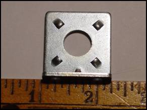
Retaining Bracket
The incorrect bracket is pictured on the left. The correct/proper replacement part is pictured on the right. The correct replacement part has four tabs that keep the base of the return spring properly in place. This placement facilitates the simultaneous collapsing and winding of the spring.
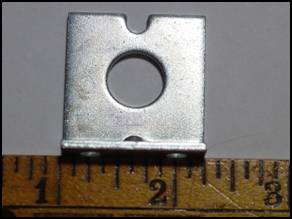
Coil Stop
The incorrect stop is pictured on the left. The correct replacement part is pictured on the right. The stop of the bracket, on the correct replacement part, is shorter than the stop on the incorrect part. The shorter stop allows for greater swing of the flipper bat and a more useable angle to hold the ball while the flipper is in the up position.
Flipper Bushing
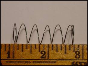
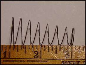
Return Spring
The wrong spring, a pop bumper spring, is pictured on the left. This spring is sometimes incorrectly sold as the replacement part; which is pictured on the right. The wrong spring will bind against the plunger when the plunger is pulled inside the flipper coil during a flip.
End Of Stroke (EOS) Switch
The incorrect EOS, on the left, is different from the correct replacement part, pictured on the right. The incorrect part has contact points that are plated with gold. Gold contacts are not designed to handle the heat and power required to flip your flippers. The correct part has tungsten contacts. Tungsten contacts are suited for this purpose. Many different pinball parts dealers have C-13174-L/R flipper parts for sale. But, be sure you get the correct part(s).
To provide the best performance for your pinball machine, you may want to completely replace your old flipper assembly (like the incomplete one above) with a brand new assembly. But, I could only find a few pinball parts dealers on-line who also have the complete C-13174-L/R flipper assemblies for sale. The dealers I have found are listed in alphabetical order.
Flip happy, flip often, and flip safely!
© Pinball News 2006 |