|
|

|
AUTOMATIC FOR THE PEOPLE
|
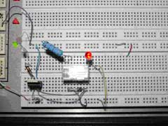
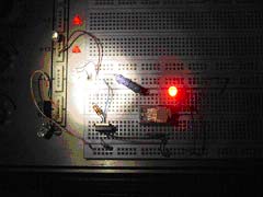
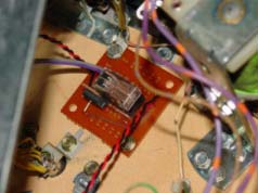
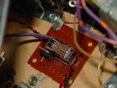
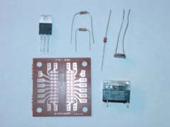
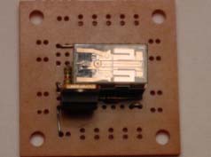
| In this third article, Todd "Pinted" Andersen, President of the TCFPA moves on from looking at lamps and LEDs to explaining how to control them with a simple circuit. Automated & Isolated - INCEPTION I grabbed a few electronic parts out of my spare parts bin. From inception to creation, I produced this neat little circuit, and tested it in a game in just a few hours. The circuit consists of just 7 - components. There are 3 - resistors, 1 - diode. 1 - relay, 1 - circuit board, and 1 - transistor. In the pictures below, the big blue resistor and red LED should be familiar from a previous article, but are not part of the circuit. They are a test replacement for the device the circuit is going to power. The operation of this small circuit is much like when you turn on your television. For the circuit, the ambient light of the general illumination lighting inside your game is like the action of you using the infrared light from your remote control to turn on your television. In the context of the circuit, the television is the relay. And the images and sounds you enjoy are akin to the device you are trying to control in or on your pinball machine.
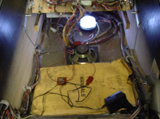
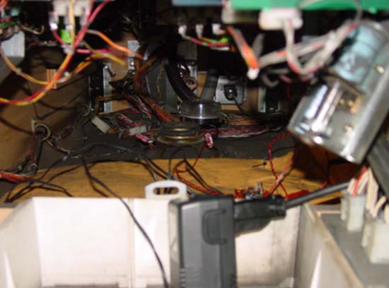
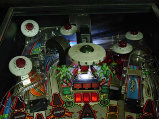
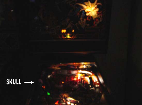
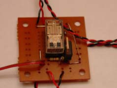
NOTE USES Here's a picture of the circuit powering an under playfield strobe light in “Attack from Mars”.
REPRODUCTION SUGGESTIONS With that in mind: a parts list, parts suppliers, and a schematic are listed at the end of this article. I did NOT list the power supply for several reasons. First, the input voltage for the transformer will vary from country-to-county or even region-to-region of the same county. The input voltage for the circuit is the same as the voltage required to run your add-on. The circuit’s designed working voltage range is: positive 9 to 18 - Volts of Direct Current. So a “9 - Volt transistor” battery could be used to power the circuit. But, small AC / DC converters, sometimes called “wall warts”, work wonderfully for this purpose. Which brings us to the second reason for NOT listing a specific voltage source, current requirements. Pick an AC / DC converter that will handle twice the estimated current consumed by your add-on. For instance, two #47 bulbs in series take about 12 Volts to operate at about 1/2 Amp. So, for this application, choose a 12 VDC, 1 Amp converter. Most LED add-ons seem to be set up to run off of +12VDC and usually have 2 - 12 LEDs. Each LED needs about 0.30 mA of current. The relay I used can easily switch these small loads. The relay will even switch small inductive loads such as small DC motors. Remember to choose a relay and power supply that match. For example, I used a +12VDC (1 Amp): power supply, relay, and add on. CONSTRUCTION
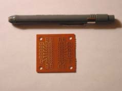
Remember that with the exception of the resistors, the parts in this circuit only go into the circuit one way. And, be careful to remember positive and negative for your input and output power connections. All parts get installed on the bare side of the circuit board. Start out by installing the: relay, diode and first three jumpers. Excess component leads or a paper clip can be used to make the jumpers. Install the transistor next. Then, bend both leads of the 1K Ohm resistor down at 90° right next to the resistor’s body. This resistor will “lie down” when installed on the board. Now, bend only one lead of the 10K Ohm resistor down at a 180° bend to this resistor’s body. Bend this lead right next to the body of the resistor. Keep he other lead straight. This resistor will “stand up” when installed on the board. Then, install the two resistors. The body of the 10K Ohm resistor should go towards the transistor and the bare lead of the 10K Ohm resistor should be mounted away from the transistor. And lastly, install your wires.
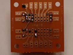
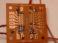
The board has been laid out to keep wire combinations together. Wires were added for: power in, power out, and sensor connections. The INput power connections are the RED (positive) and BLACK (negative) wires near the BROWN and RED SENSOR wires. The OUTput power connections are the RED (positive) and BLACK (negative) wires on the opposite side of the board. You may want to use different colored wire to keep track of INput and OUTput. Be especially sure you keep track of both of the positive and negative sets of wires. This will help ensure that you apply the correct polarity to your: pin-toppers, add-ons, or pin-mods. Use your small, flat screwdriver to “feel” in between the adjacent traces that you soldered. The screwdriver may also be used to break any solder bridges that may have inadvertently formed. Large bridges may have to be cut with the small knife. Double-check all of your work. Be especially mindful of the power input and output connections. Then, clean up the solder side of the board. I’ve found that 90% isopropyl alcohol - IPA and a toothbrush work best for cleaning solder flux residue off of circuit boards. Allow the board to dry thoroughly. Then, continue to the last step. And lastly, test the circuit out of the game before you install it. Apply power to the circuit. You will know that the circuit is probably working when you hear the tiny “click” of the relay. If you hear the click, try testing the add-on or pin-mod out of the game first. TROUBLESHOOTING This little circuit is very sensitive. If you can’t get the circuit to toggle the output power on-and-off, try making the room completely dark. Then, shine a flashlight on the light dependent resistor - your sensor. A small click should be heard from the relay and the device you are controlling should turn on. Move the flashlight’s beam away from the sensor and the device should turn off. A small click should also be heard from the relay. If you got these results, the circuit should be working properly. TOOLS Pictured below are most of the tools and supplies I used while making the relay circuit.
TOOLS LIST (clockwise) 2) Non-insulated wire (thin gauge) 3) Small Straight Screwdriver 4) Solder 5) Eraser (pen), a standard pencil eraser will work 6) Insulated stranded wire (thin gauge), stranded wire can take more flexing than solid or single strand wire 7) Small utility knife, a box knife or an “X-Acto” knife will also work well for cutting the trace or solder bridges 8) Wire Stripers 9) Side cutter 10) Needle Nose Pliers, a large tweezers will work as well INSTALLATION I secured the small circuit board with just one small wood screw in two opposite corners. DO NOT OVERTIGHTEN the screws or damage to the circuit or your game may result. Only tighten both screws to the point where the board is flush with the playfield and it is not loose; it does not wiggle when you apply slight pressure with your finger. For the circuits I built, I chose to add connectors for the: input power, sensor, and output power. But, you can use wire-nuts or solder the wires directly. I recommend the use of wires to extend the: input power, sensor, and output power. For small DC loads, there is no need for heavy gauge wires. Thin wires can be easily routed. But, be sure that the wiring itself does not interfere with the game and that the sensor can be installed at the best location for picking up the light from at least one general illumination bulb. Because of the added lengths of wire, the circuit works especially well for pin-toppers. The converter may be plugged into a nearby standard wall outlet. The circuit can be mounted behind the game’s backbox. And, the sensor can be carefully inserted through one of the vents in the backbox. Remember to run the wires so they does not interfere with the game or short anything out. Some sensors have a metal body. Ensure that when you place your sensor, it does not short anything out or interfere with the game in any way. PARTS SOURCES "Radio Shack" SUBSTITUTE PARTS SCHEMATIC
SIMPLE CIRCUIT DESCRIPTION ADVANCED CIRCUIT DESCRIPTION R1, is the Light Dependant Resistor. It’s value decreased in light and increases in darkness. R2, is used to protect the transistor and help ensure that it doesn’t go too far into saturation. R3, is the pull-down resistor. It determines the set point for the transistor to turn on. R1, R2, and R3, together make up a voltage divider bias for the transistor. This is an electrical “ladder”. At a certain position on the ladder, the transistor turns on. The level of ambient light determines the actual dynamic level. REL, is the relay. As the designed operating voltage of the circuit is from 9 to 18 - Volts of Direct Current, for my circuit, a small +12 Volt Direct Current relay was selected; the contacts of which can handle 1 - Amp of Direct Current. The relay is small enough to fit on the tiny circuit board. The relay uses the input power and switches in the same power, via a parallel path, to the device. Other relays may be substituted but the circuit may have to be slightly modified (laid out) to match the new relay’s connections. T1, the transistor is a TIP 31C. Any transistors in this family may be used. In fact, due to the simplicity of the circuit’s design, almost any NPN transistor that can handle at least 40 - Volts and 3 - Amps should work. The transistor is just used in switching mode. FINAL NOTE
|