| In a previous article, I shared a little mod/topper controller circuit with Pinball News (PBN) readers. The circuit is light dependant. That is, the circuit uses light to trigger a relay.
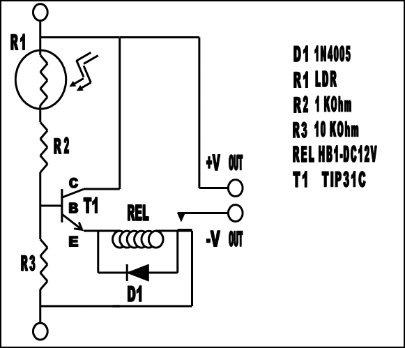
The relay controls (switches on and off) the power going to the pin-modification or pin-topper associated with your pinball machine. I have included the Light Dependant Relay – LDR circuit directly below as a reference. Because several important points are covered in the original article, I recommend that you go back and review that article before you build the little LDR circuit.

Above is the light dependent pinball add-on controller circuit from a previous article.
Some PBN readers either couldn't read schematics or found the above circuit diagram a little confusing. Admittedly, I tried to keep the above schematic minimalist. So, this schematic is not the best representation of the LDR circuit.
In response to the questions and requests of readers, I have drawn a different version of this same circuit and a new slightly modified version of the LDR circuit. These new schemata are more diagrammatic. So, I hope that you find both of the new drawings easier to follow; therefore easier to build. Keep in mind that none of the parts are drawn to scale.
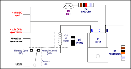
Light Detector
This circuit is the same as the above circuit. It is just drawn a little differently. The transistor is shown front-side-up but up-side-down. Also in the diagram, the items inside the dotted boxes and joined by the dotted line are actually part of the same component, a relay of your choosing.

This circuit, just a redrawn version of the original circuit, is designed to turn on a pin-modification or pin-topper when power is applied to the circuit and the remote sensor (R1/LDR ) is in the presence of the general illumination (GI) lighting inside a pinball machine. Look at only the left side of the circuit. You can see that the power is always available for the mod or topper. The contacts of the relay just act as an on/off switch for the power. Light falling on R1 operates the switch. More simply put, once light finds its way to R1, the normally open (no) contact of the relay gets closed and whatever the circuit is hooked up to gets switched on. So, to make the circuit operate the opposite way, you can simply change the ground wiring of the add-on, from the normally open contact to the normally closed (nc) contact. The wiring at the common (c) contact would just say as it is.
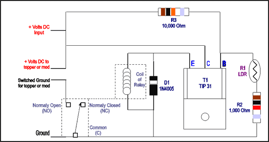
Dark Detector
This circuit uses all of the exact same components as the above circuit. As before, the transistor is shown front-side-up but up-side-down. And again, the items inside the dotted boxes and joined by the dotted line are actually part of the same component, a relay.

In this diagram, only a few of the components are flipped around to make the circuit work in the presence of darkness. This is the only major difference between the two new circuits. Though this circuit acts similarly to the fist circuit being rewired for its opposite effect, this circuit does not operate as the same thing. This circuit is designed to turn on a pin-modification or pin-topper when power is applied to the circuit and the remote sensor (R1/LDR) is in the presence of darkness. Again, look at just the left side of the circuit. You can see that the power is always available for the mod or topper. So, if this circuit were connected to a pin-topper, the topper would be lit when the game was turned off. This would draw attention to your cool topper, making the topper an awesome nightlight. The toper would also light during game play, when a blackout mode was reached; again drawing attention to your topper but making it seem more a part of the game.
Circuit Differences
If the first circuit can be wired to act like the second circuit; by merely changing the wiring from the normally open contact to the normally closed contact, why would two circuits be needed? The answer is, because both circuits are used to actively control the pin-mod or pin-topper. When the wiring of the first new circuit gets attached to the normally closed contact, the circuit would virtually be the same as the second new circuit. But, when power is applied to the circuits, they are active.
So, with use of the first new diagram, you could easily turn on a pin-add-on in conjunction with a flasher. This would make the add-on seem to respond to or seem to be a part of the pinball machine. This active process could not happen if the normally closed contact were used. In such a case, direct wiring of the add-on is recommended.
NOTE
All schematic diagrams are courtesy of  . .
 Back to the learn page Back to the learn page
 Back to the front page Back to the front page
© Pinball News 2006
|


